SLC Signal generator
Ultra-low Jitter Clock Synthesizer
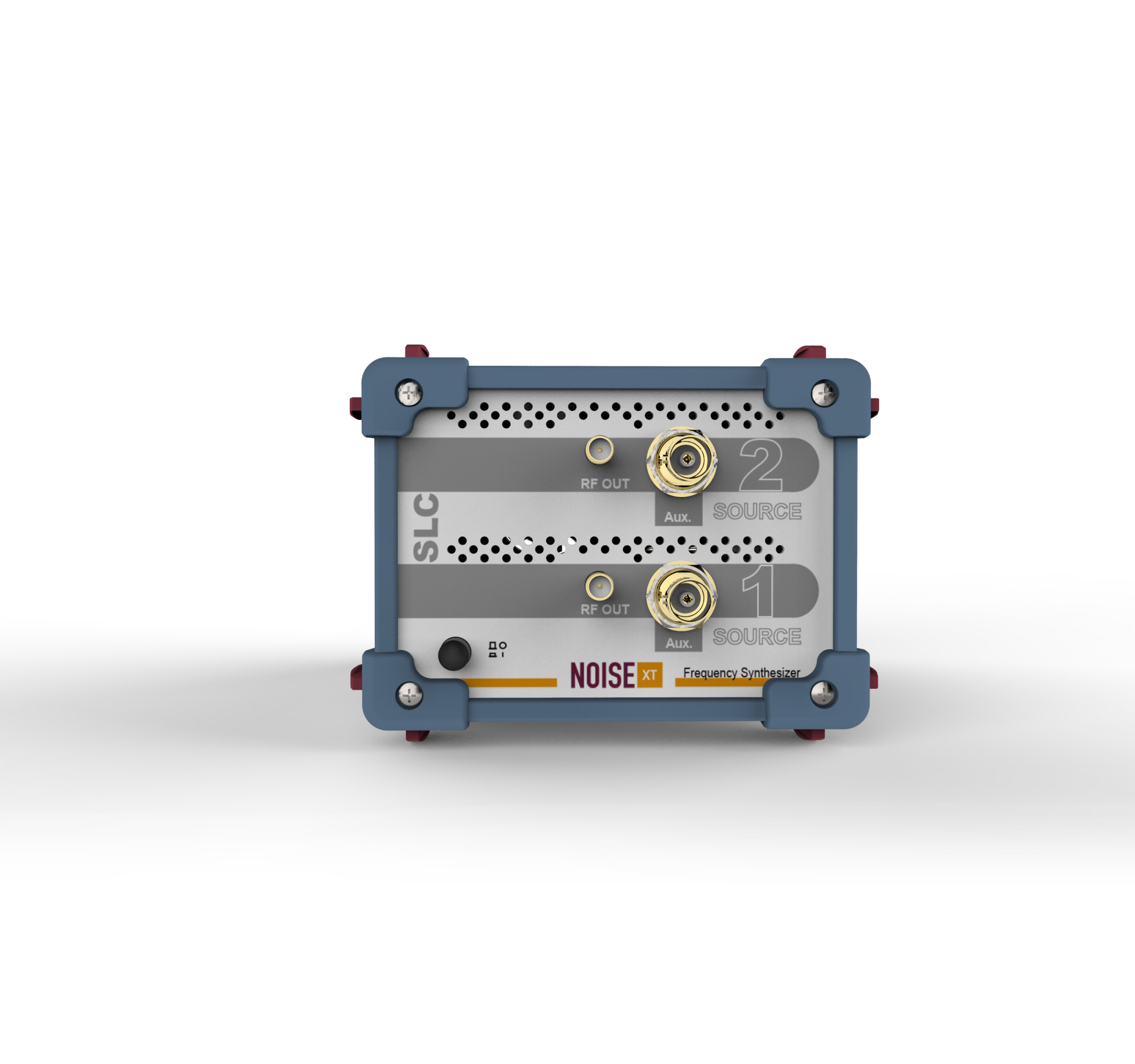
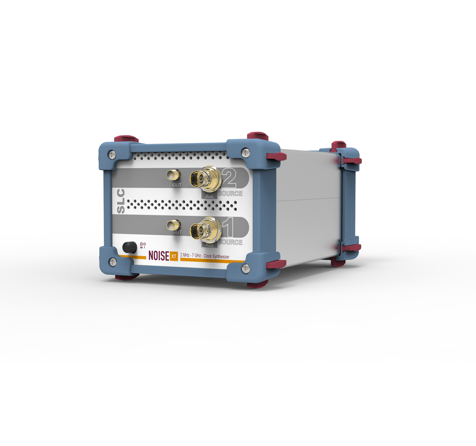
The SLC is a very affordable single or dual clock 7 GHz synthesizer that exhibits outstanding phase noise and jitter performance in a very small package.
With -178 dBc/Hz phase noise floor at 10 MHz, the SLC is the lowest phase noise compact clock synthesizer of the industry that can help you challenge tomorrow’s requirements for high speed, high bandwidth Software Defined Radio applications (SDR) and low phase noise PLL and DDS synthesis.
Its high power output is ideal to drive mixers’ LO inputs or high-speed digital clocks. Its very low jitter profile makes ADC and DAC testing more accurate. This source is often cleaner than a crystal oscillator and can offer a high SNR, up to 135 dB.
USB control helps you seamlessly integrate this tool in your test project or clock distribution architecture. Both synthesizers can be controlled completely independently and do not share any common reference frequencies. However, when coherent signals are required, they can be locked to each other with the help of their 10 MHz reference signals.
A unique feature allows multiple SLCs to align their outputs when Phase Coherence is important. Not only they are phase locked in a conventional way like other signal generators but their precise phase relationship is always the same even if you have switched to another frequency in between two measurements.
Optional ultra low phase noise OCXO allows the synthesizers to reach their best specification and if this is not enough, the external 10/100/400 MHz reference input/Outputs will extends its long term frequency stability (Allan variance) to the one of atomic clocks.
Why the SLC Series ?
- Frequency Range: 2 MHz to 7 GHz
- Phase Noise Floor: down-to -178 dBc/Hz !
- One or Two Clock synthesizers configuration
- Ultra Compact Form Factor Box
- SNR up to 135 dB
- USB control
- 0.001 Hz Resolution
- Phase alignment for Phase Coherent applications
Specifications
| SPECIFICATION | VALUE |
| Output Frequency: | 2 MHz to 7 GHz |
| Frequency Resolution: | 0.001 Hz |
| Frequency Switching time: | < 150 us (option) |
| Frequency Dwell time: | 2 ms to 20,000 ms |
| Output Level: | -30 dBm to +13 dBm (to +17 dBm in 4 MHz-4 GHz) |
| Level Resolution: | 0.5 dB |
| Non-Harmonic spurious: | -70 dBc above 1 kHz offset |
| Modulation: | DC coupled FM (8ppm/V VCXO, 0.7ppm/V OCXO option) |
| Output connector: | SMA female, 50 Ohms |
Typical Output Power Level
Below is the maximum RF output power level for the whole band. The SLC is capable of +18 dBm in most of its band and drive power demanding applications.
Phase Noise performance
Typical Phase Noise with standard phase noise installed (VCXO).
| dBc/Hz vs offset (Hz) |
100 | 1K | 10k | 100k | 1M | Floor |
|---|---|---|---|---|---|---|
| 10 MHz | -137 | -160 | -168 | -170 | -170 | -170 |
| 100 MHz | -117 | -140 | -154 | -156 | -158 | -164 |
| 1 GHz | -97 | -120 | -134 | -137 | -142 | -160 |
| 2 GHz | -90 | -113 | -128 | -126 | -129 | -160 |
| 3 GHz | -84 | -107 | -123 | -125 | -130 | -160 |
please add +5 dB for guaranteed performance
Typical Phase Noise with ultra low phase noise option installed (OCXO).
| dBc/Hz vs offset (Hz) |
100 | 1K | 10k | 100k | 1M | Floor |
|---|---|---|---|---|---|---|
| 10 MHz | -150 | -163 | -168 | -172 | -175 | -175 |
| 100 MHz | -131 | -143 | -154 | -156 | -158 | -164 |
| 1 GHz | -111 | -125 | -134 | -137 | -142 | -160 |
| 2 GHz | -106 | -120 | -128 | -126 | -129 | -160 |
| 4 GHz | -99 | -114 | -123 | -125 | -130 | -160 |
please add +5 dB for guaranteed performance
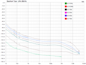
Typical Phase Noise plots at various frequencies with ultra low phase noise OCXO option
Typical Residual FM Computation
The Residual FM can be computed from the Phase Noise plots with various un-weighted bandwidth.
| RMS FM (Hz) vs carrier |
10 | 100 | 1000 | 2000 | 4000 |
|---|---|---|---|---|---|
| 50 – 3k Hz | 0.001 | 0.007 | 0.061 | 0.094 | 0.19 |
| 300 – 3.4k Hz | 0.001 | 0.008 | 0.066 | 0.107 | 0.19 |
| 20 – 15k Hz | 0.005 | 0.032 | 0.303 | 0.595 | 1.03 |
Typical RMS Jitter Computation
Based on the spectral purity of the Clock, the Jitter can be extracted.
| jitter RMS (fs) vs carrier (MHz) | 10 | 100 | 1000 | 2000 | 4000 |
|---|---|---|---|---|---|
| 10 – 1M Hz | 67 | 32 | 44 | 54 | 27 |
| 10 – 10M Hz | 66 | 81 | 78 | 33 | |
| 10 – 40M Hz | 98 | 87 | 83 | 35 | |
| 10 – 100M Hz | 89 | 84 | 36 |
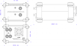
SLC Dimensions.
For more specification please download the pdf file of the library
Main Options list
- Option 1: Ultra-low noise OCXO.
- Option 2: High Speed frequency switching time < 150 us.
Documents
| File Description | File Name | Dated |
| SLC Datasheet – PDF | SLC Datasheet v3b |


